Segments and Connectors
In the Overture transportation theme, features with their type property set to segment represent paths repeatedly traversed by people or objects. For example, a segment may represent a major highway, an abandoned subway line, or a ferry route. The connector feature type carries point geometry which describes a location where a physical connection between two or more segments occurs.
Together, segments and connectors capture the shape and connectivity of the transportation network.


A connector physically joining three segments.
Connectors
The connector feature type carries point geometry representing a location where a physical connection between two or more segments occurs (or may occur in the future). Connectors have no properties apart from geometry and standard Overture feature properties. All other aspects of the transportation theme are modeled on segments.
To better support routing use cases, the segment feature type has a property called connectors: an array of IDs with pre-computed linear reference values that explicitly link segments and connector features via coordinates. Each connector is a possible routing decision point, meaning it defines a place along the segment where there is a possibility to transition to other segments that share the same connector.
Here's an example of how the connectors property is modeled in the schema:
id: overture:transportation:segment:123
type: Feature
geometry:
  type: LineString
  coordinates: [[0, 0], [0.03, 0], [0.10, 0]]
properties:
  theme: transportation
  type: segment
  version: 1
  subtype: road
  class: secondary
  connectors:
    - connector_id: fooConnector
      at: 0
    - connector_id: barConnector
      at: 0.3
    - connector_id: bazConnector
      at: 1
  road_surface:
    - value: paved
Physical connectivity
Two or more segments are physically connected at a given connector if each segment's connectors property contains a reference to the connector.
The connector geometry's coordinates should preferably be contained within the segment geometry's coordinates, in which case the connector coordinates define the point of physical connection. This constraint will always be met by official Overture data releases. Where this is not possible, the point of physical connection is the closest point to the connector coordinates which intersects the segment geometry.
Conversely, two segments are not physically connected if their connectors properties do not reference a shared connector, even if their geometries overlap or even share a coordinate in common.
Travel from a point on one segment to a point on another physically-connected segment is allowed, unless limited by an explicit restriction such as an access or turn restriction.
All segments in official Overture transportation data releases have a minimum of two connectors, one at each end of the geometry, even if those endpoint connectors are not attached to any other segment. This is done to allow new segments to connect into the existing network without needing to change the properties of existing segments.
Segments
The segment feature type carries LineString geometry which describes the physical shape of a section of the transportation network. A segment may represent an entity with a tangible real-world existence, such as a paved road, or it may represent an intangible entity, such as a ferry route, which has a well-known shape but no observable presence in the real world.
Subtypes
Because of their many possible uses, the segment type is further organized by its subtype, class, and subclass properties. Currently, the Overture transportation theme supports three segment subtypes:
| Subtype | Description | % of total segment length |
|---|---|---|
road | Roads and footpaths | ~97% |
rail | Any transit system in which vehicles ride on metal rails | ~3% |
water | Shipping lanes and ferry routes | <1% |
Geometry
A segment's geometry approximates the physical centerline of the section of path it models. For roads, information regarding the width of this path is captured in the width_rules road-specific property.
Class
The class property of a segment specifies its general purpose of use within its subtype. Unlike many segment properties, a segment's class property does not support geometric scoping (linear referencing). Consequently, whenever a linear range of real-world road or rail makes a class transition (for example, between secondary and residential roads), the Overture transportation segmentation algorithm will generate a segment split.
Currently, only roads and railways have the class property. Within these subtypes, every segment has a class. If the class property is missing from a segment's source dataset, the class for that segment will be given default value unknown, indicating the class is undetermined and may be updated in a later release.
Flags
A segment's flags (road_flags for roads, rail_flags for rails) are a set of named flag values indicating the presence or absence of simple physical characteristics. For example, a road segment with road_flags = [is_link, is_under_construction] is a link segment that is physically under construction.
Like many segment properties, the road_flags/rail_flags property supports geometric scoping. Consequently, the applicable flags may vary along different sub-ranges of a road segment's geometry.
Here's an example of how classes, subclasses, and flags are modeled in the Overture schema:
class: footway
subclass_rules:
  - value: sidewalk
    between: [0, 0.6]
  - value: crosswalk
    between: [0.6, 1.0]
road_flags:
  - values: [is_bridge]
    between: [0.2, 0.3]
  - values: [is_under_construction]
    between: [0.3, 0.5]

class: service
subclass_rules:
  - value: driveway
    between: [0, 0.5]

class: primary
subclass: link
subclass_rules:
  - value: link
Granularity
Occasionally, a real-world feature admits different representations at different granularities. For example, a dual carriageway may be modeled as one segment, or two parallel segments. Segments support modeling the transportation network at a range of granularities. A single segment can represent a bidirectional street including all of its sidewalks, a single sidewalk, two parallel subway tracks, a one-way street, or one direction of a dual carriageway.
Start, end, and orientation
The first coordinate in a segment's geometry is the start of the segment and the last coordinate is the end. A segment is oriented away from the start and toward the end.
type: LineString
coordinates:
  - [1, 0]   # Start
  - [0, 0]
  - [-1, 0]  # End


This segment geometry is oriented due west.
type: LineString
coordinates:
  - [-1, 0]  # Start
  - [0, 0]
  - [1, 0]   # End


This segment geometry is oriented due east.
Heading
Travel along a segment's geometry can follow one of two possible headings: forward or backward. The forward heading proceeds toward the end of the segment; while the backward heading proceeds back toward the start of the segment.


Travel heading along a segment.
Level (Z-order)
Segment geometry is two-dimensional. In the real, 3D, world, however the entities represented by segments can be above or below each other, as may happen with tunnels, bridges, overpasses, and stacked multi-level highway interchanges. To accurately render top-down 2D maps, it is important to know the relative stacking order, or Z-order, of segments.
Segment Z-order is given by the level property. A level value of 0 indicates visual level, with positive numbers indicating above visual level, negative numbers indicating below visual level, and in general, a lesser number indicating a lower position in the stacking order than a greater number.
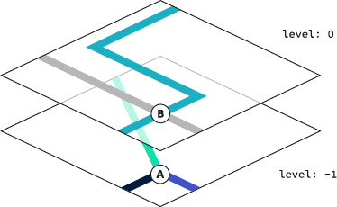
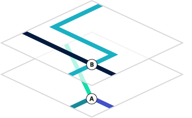
Ground level segments stacking above tunnel segments.
Note that two segments with different level values may be physically connected, since level is an approximation for rendering and is not meant be a precise indication of elevation at different points along the segment.
Destinations
The destinations property in the segment feature type supports routing use cases. It describes the transitions from one segment to another on the way to a specified location. In turn-by-turn routing applications, this is what is known as "follow signs for" — the human-readable directions and signposts along a road, highway, or interstate that get us from point A to point Z, by way of any number of paths in between. The destinations property has a flexible schema that will allow us to capture and model navigation data from many different sources.
Linear referencing
Properties on a segment can vary along its length using normalized positions from 0.0 (start) to 1.0 (end), a technique called linear referencing. For full details on how linear references work, including calculation methods, code examples, and edge cases, see the linear referencing guide.
Segmentation
The term segmentation describes the process of converting upstream source data into Overture transportation shape and connectivity data modeled as segments and connectors.
Shape stability
A primary goal of Overture's segmentation process is to promote stability of segment shape across Overture data releases. For example, if a certain real-world stretch of Main Street is represented by a single segment with particular geometry in release 1, we will strive to avoid slicing the exact same geometry up into two, three, or four segments in release 2.
Aiming for segment shape stability categorically does not mean that Overture aims for a stable transportation dataset. On the contrary, we aim to continuously improve data accuracy and coverage, and expect the transportation network dataset to constantly evolve and grow as a result. Our goal is simply to minimize unnecessary, semantically meaningless, changes in how the geometry is sliced into segments across data releases.
Several features of the transportation theme schema were designed to allow the segmentation process to achieve its segment stability goal. These features include:
- interior connectors
- geometrically scoped segment properties
ID stability
Overture pursues shape stability to improve the ability to assess whether two segments from different points in time (or from different upstream data sources) represent the same real-world entity. Overture's success at this assessment directly feeds into the stability and precision of GERS IDs assigned to segments. In turn, higher GERS ID stability and precision makes transportation theme data more useful for conflation.
Interior connectors
A key feature of the Overture transportation schema which enables shape stability is the ability of segments to support connectors at interior positions along their geometry, not only at their endpoints. The ability to add internal connectors prevents the segmentation process from having to blindly follow every split or join introduced in upstream source data.
For example, imagine a square city block bordered by road on all four sides has been mapped in the source data, but a back alley dividing the block along the east-west axis has not. If the back alley is subsequently mapped in the source data, the Overture segmentation process can connect to the transportation network without having to subdivide any existing segments by simply introducing internal connectors on the north-south road segments bordering the block to the east and west. As a result, the Overture IDs of the north-south road segments remain as they were and no data needs to be re-conflated.
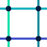

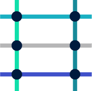

A square city block bordered by four roads before (left) and after (right) mapping the back alley using internal connectors.
Note that in the above example, an official Overture data release would insert coordinates in the middle of the north-south segments, if they did not already exist, because Overture data releases will always ensure that every segment's geometry includes all of its connectors.
Geometric scoping
Many segment properties may include a linear reference so that they apply only to a part of the segment geometry. We refer to these linearly-referenced property values as being geometrically scoped and discuss geometric scoping at greater length in the page on scoped properties.
Geometric scoping allows the segmentation algorithm to avoid introducing segment splits simply because a certain property has different values along different parts of the geometry. Like interior connectors, geometrically-scoped properties enable the segmentation process to make decisions that promote shape stability, ultimately resulting in more precise and stable Overture IDs and less churn in conflated data.


A single segment with multiple geometrically-scoped speed limit values.
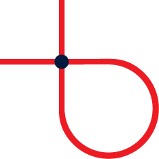
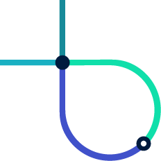
Loops
Although it is technically possible to use the Overture schema to express a segment forming a connected loop, such loops are considered invalid and will never be produced by the segmentation algorithm.
An illegal loop where one end of a segment connects to the other end can be corrected by splitting the segment and introducing a second connector to maintain physical connectivity. An illegal self-crossing loop of degree N can be corrected by splitting the segment into N pieces.


An illegal loop connected at its endpoints (left) and a possible correction (right).


An illegal self-crossing loop (left) and a possible correction (right).